Возможности микроконтроллеров и электроники безграничные и мы хотим расширять наши возможности в том, что можно сделать своими руками. Ребята из «Seeed Studio» выиграли конкурс любителей Ардуино с этим уроком по созданию мобильного телефона на базе микроконтроллера.
Объединяя Arduino и другие модули, мы сделаем мобильный телефон под названием Arduino Phone. Корпус для нашего аппарата будет напечатан с помощью 3D-принтера. Хотя получится телефон не таким хорошим как можно подумать, даже немного неуклюжим, но все равно очень крутым.

Главный минус — мы не сможем установить на Arduino Phone кучу приложений и если вы захотите поиграть в Angry Birds вам нужно будет сделать большие доработки. Давайте перейдем к уроку в котором подробно расскажем о шагах по созданию телефона Arduino, включая аппаратное соединение и реализацию программного обеспечения.
Содержание
- Шаг 1: Комплектующие
- Шаг 2: Подключение оборудования
- Шаг 3: Программирование и тестирование
- Шаг 4: Сборка
Шаг 1: Комплектующие

В самом начале, как всегда, мы готовим комплектующие. Конечно, большинство этих модулей можно приобрести напрямую, например: Arduino Uno, TFT Touch Shield и GPRS Shield.
Также мы понимаем, что мы хотим поместить наш телефон Arduino в корпус, напечатанный на 3D-принтере. Для того, чтобы адаптировать размер этого корпуса под наше устройство мы должны сделать печатную плату зарядки и разрядки (включая обе части) и плату расширения, которая сможет подключаться к гнезду для наушников GPRS Shield модуля.
Если вы хотите сделать всё самостоятельно, вы можете сразу взять, например LiPo Rider Pro — аккумуляторный зарядник, или что-то в этом роде. Таким образом, вам не нужно будет делать печатную плату самому.
Что нам нужно в итоге:
- Arduino Uno (Ардуино Уно)
- TFT Touch Shield (TFT сенсорный экран)
- GPRS модуль
- RTC модуль (Real-Time Clock, часы реального времени)
- Зарядное устройство для ArduinoPhone (либо купить готовое, например от Lipo Rider)
- Li-po баттареи
- Корпус (можно сделать на 3D-принтере)
Шаг 2: Подключение оборудования


После подготовки деталей нам необходимо собрать вышеуказанные электронные компоненты вместе, чтобы заложить фундаментную функциональную часть Arduino Phone.
- Подключите GPRS модуль к Arduino UNO, затем подключите дисплей к GPRS.
- Подключите модуль RTC к Arduino UNO.
- Вставьте модуль питания и подключите наушник к разъему для наушников на GPRS.
Хорошо, теперь мы займемся программным обеспечением.
Шаг 3: Программирование и тестирование

Этот телефон Arduino содержит следующие основные функции:
- Принимать и отправлять сообщения, ввод букв.
- Набирать номер и отвечать на звонки.
- Отображать часы в реальном времени.
- Удобный и сжатый пользовательский интерфейс, вы можете переключать функции, передвигая палец по экрану.
- Стандартный 12-кнопочный метод ввода для сообщений.
Код для телефона Arduino и все нужные библиотеки скачайте с сайта — Github.
Непосредственно код для телефона:
#include <SeeedTouchScreen.h>
#include <SoftwareSerial.h>
#include <SPI.h>
#include <TimerOne.h>
#include <Wire.h>
//#include <TFT.h> // use TFT v1
#include <TFTv2.h> // use TFT v2
#include "phone.h"
#include "UI_ArduinoPhone_dfs.h"
#include "UI_ArduinoPhone.h"
// serial data
char serialDta[100];
unsigned char serialDtaCnt = 0; // when use data, it shoule be changed to zero(0)
bool serialGot = false; // when use data, it shoule be changed to false
// serial event
void __serialEvent()
{
disableTimer(); // disable timer irq
while (Serial.available()) {
char inChar = (char)Serial.read();
serialDta[serialDtaCnt++]= inChar;
if (inChar == 'n') {
serialGot = true;
serialDta[serialDtaCnt] = '';
break;
}
}
enableTimer(); // enable timer irq
}
int strdo(char *str)
{
int sum = 0;
//str_get(str);
while(*(str)<'A' || *(str)>'Z')str++;
if(*(str+12)>'0' && *(str+12)<'9')// >10
{
sum = (*(str+11)-'0')*10 + (*(str+12)-'0');
}
else
sum = (*(str+11)-'0');
return sum;
}
//const unsigned char __numAbc[10][6] PROGMEM =
char __numAbc[10][5] =
{
{' ', '0', ' ', ' ', ' '},
{',', '.', '!', '1', ' '},
{'a', 'b', 'c', '2', ' '},
{'d', 'e', 'f', '3', ' '},
{'g', 'h', 'i', '4', ' '},
{'j', 'k', 'l', '5', ' '},
{'m', 'n', 'o', '6', ' '},
{'p', 'q', 'r', 's', '7'},
{'t', 'u', 'v', '8', ' '},
{'w', 'x', 'y', 'z', '9'},
};
//const unsigned char __numAbcBit[10] PROGMEM =
unsigned char __numAbcBit[10] =
{
2, 4, 4, 4, 4, 4, 4, 5, 4, 5,
};
// test if call in or msg in , return 0: return : break; stateNow, state
bool checkMsgCall(unsigned char stateNow)
{
if(Phone.isMsg(serialDta))
{
UI.state_buf = stateNow;
UI.state = ST_GETSMS;
serialGot = false;
serialDtaCnt = 0;
UI.msgReadCodeMax = strdo(serialDta);
return true;
}
if(Phone.isCall(serialDta))
{
serialGot = false;
serialDtaCnt = 0;
UI.state_buf = stateNow;
UI.state = ST_GETCALL;
return true;
}
serialGot = false;
serialDtaCnt = 0;
return 0;
}
//state machine
long time1 = 0;
void stateMachine()
{
switch(UI.state)
{
//***************************************main page*************************
case ST_TIME:
Tft.fillScreen();
UI.getTime();
UI.drawTimeDate(25, 90);
UI.showMainPage();
time1 = millis();
while(1)
{
// get call
long time = millis();
if(time - time1 > 1000)
{
time1 = time;
UI.getTime();
if(UI.minute != UI.minute_buf)
{
UI.drawTimeDate(25, 90);
}
}
if(serialGot)
{
disableTimer();
if(checkMsgCall(ST_TIME)){ enableTimer();break;}
enableTimer();
}
if(UI.isTouch())// get touch
{
if(UI.getTouchRect(12, 200, 112, 270)) // phone
{
UI.state = ST_CALL;
UI.state_buf = ST_TIME;
break;
}
else if(UI.getTouchRect(128, 200, 228, 270)) // sms
{
UI.state = ST_MSG;
UI.state_buf = ST_TIME;
break;
}
}
}
break;
//***************************************phone*****************************
case ST_CALL:
if(UI.state_buf == ST_MSG)
{
UI.drawDialogBox();
UI.showCall();
}
else
{
Tft.fillScreen();
UI.drawDialogBox();
UI.showPageKB();
UI.showCall();
}
while(1)
{
if(UI.isTouch())
{
while(1)
{
stateCall();
if(serialGot)
{
if(checkMsgCall(ST_CALL))break;
}
if(UI.state != ST_CALL)break;
}
}
if(serialGot){
disableTimer();
if(checkMsgCall(ST_CALL)){enableTimer();break;}
enableTimer();
}
// check if call in or msg
if(UI.state != ST_CALL)break;
}
UI.callCount = 0;
break;
//***************************************make phone calling***************
case ST_CALLING:
Tft.fillScreen();
Tft.drawString("calling...", 20, 100, 3, WHITE);
Tft.fillRectangle(10, 200, 230, 50, GRAY1);
Tft.drawString("HANDUP", 20, 215, 3, RED);
while(1)
{
if(UI.getTouchRect(10, 200, 240, 250))// hand up
{
Phone.handUpCall();
UI.state = UI.state_buf;
UI.state_buf = ST_CALLING;
break;
}
// serial get data
if(serialGot)
{
disableTimer();
#if I2CUART
UI.I2C_Uart(serialDta);
#endif
if(Phone.isCallOver(serialDta))
{
UI.state = UI.state_buf;
UI.state_buf = ST_CALLING;
enableTimer();
break;
}
serialGot = false;
serialDtaCnt = 0;
enableTimer();
delay(1);
}
}
Tft.drawString("calling...", 20, 100, 3, BLACK);
Tft.fillRectangle(10, 200, 230, 50, BLACK);
Tft.drawString("HANDUP", 20, 215, 3, BLACK);
break;
//***************************************get call*************************
case ST_GETCALL:
Tft.fillScreen();
Tft.drawString("calling...", 20, 100, 2, WHITE);
Tft.fillRectangle(10, 200, 100, 50, GRAY1);
Tft.fillRectangle(130, 200, 100, 50, GRAY1);
Tft.drawString("ACCEPT", 15, 215, 2, GREEN);
Tft.drawString("HANDUP", 135, 215, 2, RED);
while(1)
{
// serial get data
if(serialGot)
{
disableTimer();
if(Phone.isCallOver(serialDta))
{
UI.state = UI.state_buf;
UI.state_buf = ST_GETCALL;
enableTimer();
break;
}
serialGot = false;
serialDtaCnt = 0;
enableTimer();
}
if(UI.getTouchRect(10, 200, 110, 250))// accept
{
Phone.acceptCall();
Tft.drawString("calling...", 20, 100, 2, BLACK);
Tft.drawString("call connected!", 20, 100, 2, WHITE);
Tft.drawString("call connected!", 20, 100, 2, BLACK);
}
// hand up
if(UI.getTouchRect(130, 200, 230, 250)) // hand up
{
UI.state = UI.state_buf;
UI.state_buf = ST_GETCALL;
Phone.handUpCall();
break;
}
}
Tft.fillRectangle(10, 200, 100, 50, BLACK);
Tft.fillRectangle(130, 200, 100, 50, BLACK);
break;
//***************************************message***************************
case ST_MSG:
if(UI.state_buf == ST_CALL)
{
UI.drawMsgDialogBox();
UI.showMsg();
}
else
{
Tft.fillScreen();
UI.showPageKB();
UI.drawMsgDialogBox();
UI.showMsg();
}
while(1)
{
if(UI.isTouch())
{
while(1)
{
stateMsg();
if(UI.state != ST_MSG)break;
if(serialGot)
{
disableTimer();
if(checkMsgCall(ST_MSG)){enableTimer();break;}
enableTimer();
}
}
}
if(serialGot)
{
disableTimer();
if(checkMsgCall(ST_MSG)){enableTimer();break;}
enableTimer();
}
if(UI.state != ST_MSG)break;
}
UI.msgCount = 0;
UI.msgNumCount = 0;
break;
//***************************************message sending*******************
case ST_SENDSMS:
Tft.fillScreen();
Tft.drawString("SMS Sending", 20, 120, 3, WHITE);
while(1)
{
// delay(1000);
if(Phone.isMsgSendOver())
{
UI.state_buf = ST_SENDSMS;
UI.state = ST_MSG;
break;
}
}
Tft.drawString("SMS Sending", 20, 120, 3, BLACK);
break;
//**************************************get msg******************************
case ST_GETSMS:
UI.drawReadMsgPage();
// get new msg
Serial.print("AT+CMGR=");Serial.println(UI.msgReadCodeMax, DEC);
UI.msgReadCodeNow = UI.msgReadCodeMax;
while(1)
{
stateMsgRead();
if(UI.state != ST_GETSMS)
break;
}
break;
default:
;
}
}
// state: phone call
void stateCall()
{
unsigned char button = 0;
long timercall = millis();
UI.getTouch(&button);
long t = millis();
if(button>0 && button<10)
{
UI.callAdd(button);
}
else if(button == 11)
{
long deltT = t - timercall;
if((UI.callCount < 1) && (deltT>400))
{
UI.callAdd(15);
}
else UI.callAdd(0);
}
else if(button == 12)
{
UI.callDel();
}
else if(button == 10)// call
{
Phone.makeCall();
UI.callCount = 0;
UI.state_buf = ST_CALL;
UI.state = ST_CALLING;
}
else if(button == TOUCH_DRAG_LEFT)
{
UI.state_buf = ST_CALL;
UI.state = ST_MSG;
}
else if(button == TOUCH_DRAG_RIGHT)
{
UI.state_buf = ST_CALL;
UI.state = ST_TIME;
}
}
// state: message
void stateMsg()
{
long time = millis();
long time1 = time;
unsigned char buttonNum = 100;
unsigned char buttonNumBuf = 100;
int count = 0;
unsigned char button = 0;
char let2[4] = {'a', 'b', 'c', '4'};
if(!UI.isTouch())return;
unsigned char msgState = 1;
while(1)
{
long time1 = millis();
msgState = UI.getMsgInputState();
if(msgState == 1)
{
UI.state_msg = MSG_STATE_NUM;
delay(100);
button = 0;
}
else if(msgState == 2)
{
UI.state_msg = MSG_STATE_TXT;
delay(100);
button = 0;
}
else
{
button = UI.getTouch(&button);
}
// input txt
if(button == TOUCH_DRAG_LEFT)
{
UI.state_buf = ST_MSG;
UI.state = ST_GETSMS;
break;
}
else if(button == TOUCH_DRAG_RIGHT)
{
UI.state_buf = ST_MSG;
UI.state = ST_CALL;
break;
}
else if(button>0 && button<10)
{
if(UI.state_msg == MSG_STATE_TXT)
{
buttonNum = button;
UI.msgAdd(__numAbc[buttonNum][count % __numAbcBit[buttonNum]], RED);
count++;
time = time1;
}
else
{
buttonNum = button;
UI.msgNumAdd(buttonNum);
buttonNum = 100;
}
}
else if(button == 11)//0
{
if(UI.state_msg == MSG_STATE_TXT)
{
buttonNum = 10;
UI.msgAdd(__numAbc[0][count % __numAbcBit[0]], RED);
count++;
time = time1;
}
else
{
long t = millis();
long deltT = t - time1;
if(deltT > 500 && UI.msgNumCount == 0)
UI.msgNumAdd(15);
else
UI.msgNumAdd(0);
buttonNum = 100;
}
}
else if(button == 12) // del
{
if(UI.state_msg == MSG_STATE_TXT)
UI.msgDel();
else
UI.msgNumDel();
break;
}
else if(button == 10) // send
{
Phone.msgSend();
UI.state_buf = ST_MSG;
UI.state = ST_SENDSMS;
break;
}
if(((time1 - time) > 600)&& UI.state_msg == MSG_STATE_TXT)
{
if(buttonNum>0 && buttonNum<10)UI.msgAdd(__numAbc[buttonNum][(count-1) % __numAbcBit[buttonNum]]);
else if(buttonNum == 10)UI.msgAdd(__numAbc[0][(count-1) % 2]);
break;
}
}
}
// state read msg
void stateMsgRead()
{
unsigned char button = 0;
unsigned char button1 = 0;
unsigned char cnt = 0;
unsigned flag_getMsgTime = 0;
char s[20];
while(1)
{
if(serialGot)
{
disableTimer();
#if I2CUART
UI.I2C_Uart(serialDta);
delay(5);
#endif
if(flag_getMsgTime == 1)// get msg
{
#if I2CUART
int sss = UI.getReadMsgMsg(serialDta);
#else
UI.getReadMsgMsg(serialDta);
#endif
#if I2CUART
sprintf(s, "txt long = %drn", sss);
UI.I2C_Uart(s);
delay(5);
UI.I2C_Uart("rntxt:t");
delay(5);
UI.I2C_Uart(UI.msgReadTxt);
delay(5);
UI.I2C_Uart("rn");
#endif
UI.drawReadMsg();
flag_getMsgTime = 0;
}
else if(UI.getReadMsgTimeAndFrom(serialDta, UI.msgReadNum, UI.msgReadTime))
{
#if I2CUART
UI.I2C_Uart("num:t");
delay(5);
UI.I2C_Uart(UI.msgReadNum);
delay(5);
UI.I2C_Uart("rndate:t");
delay(5);
UI.I2C_Uart(UI.msgReadTime);
UI.I2C_Uart("rn");
#endif
flag_getMsgTime = 1;
}
serialGot = false;
serialDtaCnt = 0;
enableTimer();
}
if(UI.isTouch())
{
if(UI.getTouchRect(0, 270, 239, 319))
{
//UI.state = UI.state_buf;
UI.state = UI.state_buf;
UI.state_buf = ST_GETSMS;
button1 = 0;
break;
}
else button1 = UI.getTouch(&button);
}
else button1 = 0;
//drag right: read format
if(button1 == TOUCH_DRAG_RIGHT)
{
button1 = 0;
cnt = 0;
if(UI.msgReadCodeNow>2)
UI.msgReadCodeNow--;
Serial.print("AT+CMGR=");Serial.println(UI.msgReadCodeNow, DEC);
}
//drag left: read <-- msg
else if(button1 == TOUCH_DRAG_LEFT)
{
cnt = 0;
button1 = 0;
//if(UI.msgReadCodeNow<UI.msgReadCodeMax && UI.msgReadCodeMax != 1)
UI.msgReadCodeNow++;
Serial.print("AT+CMGR=");Serial.println(UI.msgReadCodeNow, DEC);
}
// return
}
}
// setup
void enableTimer()
{
Timer1.attachInterrupt(__serialEvent);
}
void disableTimer()
{
Timer1.detachInterrupt();
}
//setup
void setup()
{
Phone.init();
UI.init();
Wire.begin();
Timer1.initialize(10000); // 10 ms
Timer1.attachInterrupt(__serialEvent); // attach the service routine here
}
// loop
void loop()
{
stateMachine();
}
/*********************************************************************************************************
END FILE
*********************************************************************************************************/ Небольшая инструкция:
- Когда вы перейдете на страницу github, найдите кнопку «Загрузить ZIP», нажмите, чтобы загрузить код.
- Загруженный вами код не является библиотекой Arduino, это скетч, который включает в себя все библиотеки, которые нужны проекту.
- Разархивируйте файл, который вы загрузили из github, вы увидите папку с именем ArduinoPhone-master.
- Откройте свою среду разработки Arduino, нажмите Файл → Настройки → Расположение эскиза (File > Preferences > Sketchbook Location), перейдите к указанной выше папке — ArduinoPhone-master. Затем нажмите «ОК», чтобы сохранить.
- Закройте и снова откройте Arduino IDE, нажмите Файл → Альбом → Телефонный код (File > Sketchbook > PhoneCode), затем откроется основной код телефона Arduino.
- Выберите правильную плату и порт для загрузки кода.
Вам помогут изображения выше.
Однако гораздо более сложная проблема заключается в том, что у этого телефона Arduino нет физических кнопок (кроме кнопки сброса и GPRS). Таким образом, управление пользовательским интерфейсом будет сложной задачей. К счастью, TFT-дисплей не только предоставляет функцию отображения, но и функцию сенсорного экрана.
Таким образом, мы можем управлять пользовательским интерфейсом с помощью жестов, движений влево и вправо. На фото выше видно как работает ArduinoPhone.
В конце откройте ArduinoPhone.ino с помощью Arduino IDE, а затем загрузите исходный код в телефон.
Шаг 4: Сборка


Чтобы сделать наше устройство похожим на телефон, мы напечатали корпус на 3D-принтере, как показано выше. Затем аккуратно всё собираем. Это сложный, но интересный процесс. На самом деле, может быть, это будет даже более интересным, чем работа с кодом.

В ближайших уроках мы планируем опубликовать продолжение — обновленную версию телефона Arduino. Если у вас есть какие-либо идеи или вы готовы помочь нам разработать более совершенный интерфейс — пишите нам.
5 апреля 2018 в 15:49
| Обновлено 7 декабря 2019 в 02:16 (редакция)
Опубликовано:
Уроки, Arduino
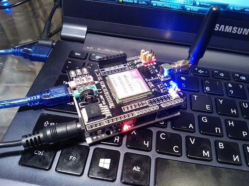
Иногда у начинающих радиолюбителей возникают трудности при реализации основных функций GSM модуля (совершение вызовов, передача текстовых сообщений и т.д.) с помощью микроконтроллеров. Поэтому в данной статье мы спроектируем простой мобильный телефон на основе платы Arduino, в котором с помощью GSM модуля можно будет делать звонки, отвечать на звонки, передавать и принимать SMS. Также наш простейший мобильный телефон на Arduino будет иметь микрофон и динамик для осуществления голосовых вызовов. Также этот проект можно рассматривать как «правильное» подключение GSM модуля к Arduino, с программным кодом, реализующим все основные функции мобильного телефона.

Необходимые компоненты
- Плата Arduino Uno (купить на AliExpress).
- GSM модуль SIM900 (купить на AliExpress).
- ЖК дисплей 16х2 (купить на AliExpress).
- Клавишная панель (клавиатура) 4×4 (купить на AliExpress).
- Микрофон.
- Динамик.
- SIM-карта.
- Источник питания.
- Макетная плата или печатная плата.
- Соединительные провода.
Принципы работы проекта
В рассматриваемом нами проекте плата Arduino Uno управляет всеми процессами. Буквенно-цифровая клавишная панель 4×4 используется в качестве универсального устройства ввода: для ввода номера мобильного абонента, набора сообщений, осуществления вызова, приема вызова, передачи SMS, приема SMS и т.д. GSM модуль используется для взаимодействия с сетью GSM. Микрофон и динамик используются для передачи и приема голоса. ЖК дисплей 16×2 используется для отображения различных сообщений. Структурная схема рассматриваемого устройства приведена на следующем рисунке.

С помощью буквенно-цифровой клавишной панели можно осуществлять ввод как букв, так и цифр. Более подробно о работе с ней вы можете прочитать в статье про подключение клавишной панели к Arduino.
Все команды в рассматриваемом нами проекте вводятся с буквенно-цифровой клавишной панели. Более подробно все аспекты функционирования проекта можно посмотреть в видео в конце статьи.
1. Осуществление вызова.
Для осуществления вызова на нашем устройстве мы должны нажать клавишу ‘C’ и затем набрать с помощью клавишной панели номер интересующего нас мобильного абонента. После набора номера необходимо снова нажать ‘C’. После этого плата Arduino начнет процесс соединения с набранным номером при помощи использования AT команд.
ATDxxxxxxxxxx; <Enter> где xxxxxxxxx – набранный мобильный номер
2. Прием вызова.
Когда кто то будет звонить на номер SIM-карты, которая вставлена в ваш GSM модуль, устройство будет высвечивать на экране ЖК дисплея сообщение ‘Incoming…’ и после него номер вызывающего абонента. Чтобы принять вызов необходимо нажать ‘A’. При нажатии этой кнопки Arduino передает соответствующую команду на GSM модуль:
ATA <enter>
3. Передача SMS.
Для передачи SMS с помощью нашего устройства мы должны нажать на клавишной панели клавишу ‘B’. После этого система запросит номер (сообщение ‘to whom’), на который необходимо передать SMS. После набора номера необходимо нажать ‘D’ и после этого ЖК экран запросит текст SMS. После этого необходимо с помощью клавишной панели ввести текст SMS так, как вы это делаете на обычном мобильном телефоне и снова нажать ‘D’ для передачи SMS. Для передачи SMS плата Arduino передает на GSM модуль следующую команду.
AT+CMGF=1 <enter>
 AT+CMGS=”xxxxxxxxxx” <enter> where: xxxxxxxxxx is entered mobile number
И передать 26 на GSM модуль для передачи SMS.
4. Прием и чтение SMS.
В этом случае GSM модуль принимает входящее SMS и сохраняет его на SIM-карте. Плата Arduino непрерывно мониторит принятые SMS через универсальный последовательный приемопередатчик (последовательный порт). Когда мы будем видеть на экране ЖК дисплея символ, свидетельствующий о поступлении нового SMS, нам необходимо будет нажать ‘D’ чтобы прочесть это SMS. Для выполнения этих операций необходимо на GSM модуль передать следующие команды:
+CMTI: “SM” <SMS stored location>
 +CMTI: “SM”,6 Where 6 is message location where it stored in SIM card.
Когда Arduino получает индикацию ‘SMS received’ оно извлекает (находит) место хранения SMS и передает команду на GSM модуль прочесть принятое SMS. После этого на экране ЖК дисплея высвечивается сообщение ‘New Message Symbol’.
AT+CMGR=<SMS stored location><enter>
 AT+CMGR=6
После этих команд GSM модуль передает хранившееся сообщение в Arduino, после чего Arduino извлекает главное SMS и отображает его на ЖК дисплее. После прочтения SMS на экран ЖК дисплея выдается сообщение ‘New SMS symbol’.
Более подробно все описанные процессы вы можете посмотреть в видео в конце статьи.
Работа схемы
Схема устройства представлена на следующем рисунке.

Контакты RS, EN, D4, D5, D6 и D7 ЖК дисплея 16×2 подключены к контактам Arduino 14, 15, 16, 17, 18 и 19. Контакты Rx и Tx GSM модуля подключены к контактам D3 и D2 платы Arduino соответственно. Земля (Ground) GSM модуля и платы Arduino должны быть соединены вместе.
Контакты строк клавишной панели 4×4 подключены R1, R2, R3, R4 непосредственно соединены с контактами 11,10, 9, 8 платы Arduino, а контакты ее столбцов C1, C2, C3, C4 соединены с контактами Arduino 7, 6, 5, 4. Микрофон (MIC) подключен к контактам mic+ и mic- GSM модуля, а динамик (Speaker) подключен к контактам SP+ и SP- GSM модуля.
Исходный код программы
Для использования клавишной панели мы в программе должны подключить библиотеку <Keypad.h>, а для ввода цифр с помощью этой клавишной панели мы должны создать функцию void alfakey(). Смысл создания этой функции заключается в том, чтобы мы могли вводить любые символы (буквы и цифры) с использованием всего 10 клавиш, находящихся на клавишной панели.
То есть если мы нажмем клавишу 2 (abc2), то на экране ЖК дисплея отобразится ‘a’, а если мы нажмем эту клавишу снова, то ‘a’ заменится на ‘b’, а если мы нажмем клавишу 3 раза, то ‘b’ заменится на экране дисплея на ‘c’. Если же после нажатия клавиши мы подождем некоторое время, то курсор автоматически передвинется на следующую позицию на экране ЖК дисплея, после чего мы сможем вводить новую цифру или букву. Аналогичные процессы будут происходить и при нажатии всех остальных клавиш.
#include <Keypad.h>
 const byte ROWS = 4; //четыре строки
 const byte COLS = 4; //четыре столбца
 char hexaKeys[ROWS][COLS] =
 {
  {'1','2','3','A'},
  {'4','5','6','B'},
  {'7','8','9','C'},
  {'*','0','#','D'}
 };
 byte rowPins[ROWS] = {11, 10, 9, 8}; //соединение с контактами строк клавиатуры
 byte colPins[COLS] = {7, 6, 5, 4}; // соединение с контактами столбцов клавиатуры
 //инициализация класса NewKeypad
 Keypad customKeypad = Keypad( makeKeymap(hexaKeys), rowPins, colPins, ROWS, COLS);
void alfakey()
 {
  int x=0,y=0;
  int num=0;
  while(1)
  {
  lcd.cursor();
  char key=customKeypad.getKey();
  if(key)
  {
  if(key=='1')
  {
  num=0;
  lcd.setCursor(x,y);
  .... .....
  ........ ....
Но кроме функций работы с клавиатурой мы должны создать несколько других функций для работы с GSM модулем: void call() – для совершения вызова, void sms() – для передачи SMS, void lcd_status() – для отображения статуса ЖК дсиплея, gsm_init() – для инициализации GSM модуля и т.д.
Далее представлен полный текст программы.
| 1 2 3 4 5 6 7 8 9 10 11 12 13 14 15 16 17 18 19 20 21 22 23 24 25 26 27 28 29 30 31 32 33 34 35 36 37 38 39 40 41 42 43 44 45 46 47 48 49 50 51 52 53 54 55 56 57 58 59 60 61 62 63 64 65 66 67 68 69 70 71 72 73 74 75 76 77 78 79 80 81 82 83 84 85 86 87 88 89 90 91 92 93 94 95 96 97 98 99 100 101 102 103 104 105 106 107 108 109 110 111 112 113 114 115 116 117 118 119 120 121 122 123 124 125 126 127 128 129 130 131 132 133 134 135 136 137 138 139 140 141 142 143 144 145 146 147 148 149 150 151 152 153 154 155 156 157 158 159 160 161 162 163 164 165 166 167 168 169 170 171 172 173 174 175 176 177 178 179 180 181 182 183 184 185 186 187 188 189 190 191 192 193 194 195 196 197 198 199 200 201 202 203 204 205 206 207 208 209 210 211 212 213 214 215 216 217 218 219 220 221 222 223 224 225 226 227 228 229 230 231 232 233 234 235 236 237 238 239 240 241 242 243 244 245 246 247 248 249 250 251 252 253 254 255 256 257 258 259 260 261 262 263 264 265 266 267 268 269 270 271 272 273 274 275 276 277 278 279 280 281 282 283 284 285 286 287 288 289 290 291 292 293 294 295 296 297 298 299 300 301 302 303 304 305 306 307 308 309 310 311 312 313 314 315 316 317 318 319 320 321 322 323 324 325 326 327 328 329 330 331 332 333 334 335 336 337 338 339 340 341 342 343 344 345 346 347 348 349 350 351 352 353 354 355 356 357 358 359 360 361 362 363 364 365 366 367 368 369 370 371 372 373 374 375 376 377 378 379 380 381 382 383 384 385 386 387 388 389 390 391 392 393 394 395 396 397 398 399 400 401 402 403 404 405 406 407 408 409 410 411 412 413 414 415 416 417 418 419 420 421 422 423 424 425 426 427 428 429 430 431 432 433 434 435 436 437 438 439 440 441 442 443 444 445 446 447 448 449 450 451 452 453 454 455 456 457 458 459 460 461 462 463 464 465 466 467 468 469 470 471 472 473 474 475 476 477 478 479 480 481 482 483 484 485 486 487 488 489 490 491 492 493 494 495 496 497 498 499 500 501 502 503 504 505 506 507 508 509 510 511 512 513 514 515 516 517 518 519 520 521 522 523 524 525 526 527 528 529 530 531 532 533 534 535 536 537 538 539 540 541 542 543 544 545 546 547 548 549 550 551 552 553 554 555 556 557 558 559 560 561 562 563 564 565 566 567 568 569 570 571 572 573 574 575 576 577 578 579 580 581 582 583 584 585 586 587 588 589 590 591 592 593 594 595 596 597 598 599 600 601 602 603 604 605 606 607 608 609 610 611 612 613 614 615 616 617 618 619 620 621 622 623 624 625 626 627 628 629 630 631 632 633 634 635 636 637 638 639 640 641 642 643 644 645 646 647 648 649 650 651 652 653 654 655 656 657 658 659 660 661 662 663 664 665 666 667 668 669 670 671 672 673 674 675 676 677 678 679 680 681 682 683 684 685 686 687 688 689 690 691 692 693 694 695 696 697 698 699 700 701 702 703 704 705 706 707 708 709 710 711 712 713 714 715 716 717 718 719 720 721 722 723 724 725 726 | #include <SoftwareSerial.h> // библиотека последовательной связи SoftwareSerial Serial1(2, 3); // контакты RX, TX нового последовательного порта #include<LiquidCrystal.h> // библиотека для работы с ЖК дисплеем LiquidCrystal lcd(14,15,16,17,18,19); // контакты Arduino, к которым подключен ЖК дисплей byte back[8] = { 0b00000, 0b00000, 0b11111, 0b10101, 0b11011, 0b11111, 0b00000, 0b00000 }; String number=«»; String msg=«»; String instr=«»; String str_sms=«»; String str1=«»; int ring=0; int i=0,temp=0; int sms_flag=0; char sms_num[3]; int rec_read=0; int temp1=0; #include <Keypad.h> const byte ROWS = 4; //four rows const byte COLS = 4; //four columns char hexaKeys[ROWS][COLS] = { {‘1’,‘2’,‘3’,‘A’}, {‘4’,‘5’,‘6’,‘B’}, {‘7’,‘8’,‘9’,‘C’}, {‘*’,‘0’,‘#’,‘D’} }; byte rowPins[ROWS] = {11, 10, 9, 8}; //connect to the row pinouts of the keypad byte colPins[COLS] = {7, 6, 5, 4}; //connect to the column pinouts of the keypad //initialize an instance of class NewKeypad Keypad customKeypad = Keypad( makeKeymap(hexaKeys), rowPins, colPins, ROWS, COLS); String ch=«1,.?!@abc2def3ghi4jkl5mno6pqrs7tuv8wxyz90 «; void setup() { Serial1.begin(9600); lcd.begin(16,2); lcd.createChar(1, back); lcd.print(«Simple Mobile «); lcd.setCursor(0,1); lcd.print(«System Ready..»); delay(1000); gsm_init(); lcd.clear(); lcd.print(«System Ready»); delay(2000); } void loop() { serialEvent(); if(sms_flag==1) { lcd.clear(); lcd.print(«New Message»); int ind=instr.indexOf(«+CMTI: «SM»,»); ind+=12; int k=0; lcd.setCursor(0,1); lcd.print(ind); while(1) { while(instr[ind]!= 0x0D) { sms_num[k++]=instr[ind++]; } break; } ind=0; sms_flag=0; lcd.setCursor(0,1); lcd.print(«Read SMS —> D»); delay(4000); instr=«»; rec_read=1; temp1=1; i=0; } if(ring == 1) { number=«»; int loc=instr.indexOf(«+CLIP: «»); if(loc > 0) { number+=instr.substring(loc+8,loc+13+8); } lcd.setCursor(0,0); lcd.print(«Incomming… «); lcd.setCursor(0,1); lcd.print(number); instr=«»; i=0; } else { serialEvent(); lcd.setCursor(0,0); lcd.print(«Call —> C «); lcd.setCursor(0,1); lcd.print(«SMS —> B «); if(rec_read==1) { lcd.write(1); lcd.print(» «); } else lcd.print(» «); } char key=customKeypad.getKey(); if(key) { if(key== ‘A’) { if(ring==1) { Serial1.println(«ATA»); delay(5000); } } else if(key==‘C’) { call(); } else if(key==‘B’) { sms(); } else if(key == ‘D’ && temp1==1) { rec_read=0; lcd.clear(); lcd.print(«Please wait…»); Serial1.print(«AT+CMGR=»); Serial1.println(sms_num); int sms_read_flag=1; str_sms=«»; while(sms_read_flag) { while(Serial1.available()>0) { char ch=Serial1.read(); str_sms+=ch; if(str_sms.indexOf(«OK»)>0) { sms_read_flag=0; //break; } } } int l1=str_sms.indexOf(«»rn»); int l2=str_sms.indexOf(«OK»); String sms=str_sms.substring(l1+3,l2—4); lcd.clear(); lcd.print(sms); delay(5000); } delay(1000); } } void call() { number=«»; lcd.clear(); lcd.print(«After Enter No.»); lcd.setCursor(0,1); lcd.print(«Press C to Call»); delay(2000); lcd.clear(); lcd.print(«Enter Number:»); lcd.setCursor(0,1); while(1) { serialEvent(); char key=customKeypad.getKey(); if(key) { if(key==‘C’) { lcd.clear(); lcd.print(«Calling……..»); lcd.setCursor(0,1); lcd.print(number); Serial1.print(«ATD»); Serial1.print(number); Serial1.println(«;»); long stime=millis()+5000; int ans=1; while(ans==1) { while(Serial1.available()>0) { if(Serial1.find(«OK»)) { lcd.clear(); lcd.print(«Ringing….»); int l=0; str1=«»; while(ans==1) { while(Serial1.available()>0) { char ch=Serial1.read(); str1+=ch; if(str1.indexOf(«NO CARRIER»)>0) { lcd.clear(); lcd.print(«Call End»); delay(2000); ans=0; return; } } char key=customKeypad.getKey(); if(key == ‘D’) { lcd.clear(); lcd.print(«Call End»); delay(2000); ans=0; return; } if(ans==0) break; } } } } } else { number+=key; lcd.print(key); } } } } void sms() { lcd.clear(); lcd.print(«Initilising SMS»); Serial1.println(«AT+CMGF=1»); delay(400); lcd.clear(); lcd.print(«After Enter No.»); lcd.setCursor(0,1); lcd.print(«Press D «); delay(2000); lcd.clear(); lcd.print(«Enter Rcpt No.:»); lcd.setCursor(0,1); Serial1.print(«AT+CMGS=»»); while(1) { serialEvent(); char key=customKeypad.getKey(); if(key) { if(key==‘D’) { //number+='»‘; Serial1.println(«»»); break; } else { //number+=key; Serial1.print(key); lcd.print(key); } } } lcd.clear(); lcd.print(«After Enter MSG «); lcd.setCursor(0,1); lcd.print(«Press D to Send «); delay(2000); lcd.clear(); lcd.print(«Enter Your Msg»); delay(1000); lcd.clear(); lcd.setCursor(0,0); alfakey(); } void alfakey() { int x=0,y=0; int num=0; while(1) { lcd.cursor(); char key=customKeypad.getKey(); if(key) { if(key==‘1’) { num=0; lcd.setCursor(x,y); lcd.print(ch[num]); for(int i=0;i<3000;i++) { lcd.noCursor(); char key=customKeypad.getKey(); if(key==‘1’) { num++; if(num>5) num=0; lcd.setCursor(x,y); lcd.print(ch[num]); i=0; delay(200); } } x++; if(x>15) { x=0; y++; y%=2; } msg+=ch[num]; } else if(key==‘2’) { num=6; lcd.setCursor(x,y); lcd.print(ch[num]); for(int i=0;i<3000;i++) { lcd.noCursor(); char key=customKeypad.getKey(); if(key==‘2’) { num++; if(num>9) num=6; lcd.setCursor(x,y); lcd.print(ch[num]); i=0; delay(200); } } x++; if(x>15) { x=0; y++; y%=2; } msg+=ch[num]; } else if(key==‘3’) { num=10; lcd.setCursor(x,y); lcd.print(ch[num]); for(int i=0;i<3000;i++) { lcd.noCursor(); char key=customKeypad.getKey(); if(key==‘3’) { num++; if(num>13) num=10; lcd.setCursor(x,y); lcd.print(ch[num]); i=0; delay(200); } } x++; if(x>15) { x=0; y++; y%=2; } msg+=ch[num]; } else if(key==‘4’) { num=14; lcd.setCursor(x,y); lcd.print(ch[num]); for(int i=0;i<3000;i++) { lcd.noCursor(); char key=customKeypad.getKey(); if(key==‘4’) { num++; if(num>17) num=14; lcd.setCursor(x,y); lcd.print(ch[num]); i=0; delay(200); } } x++; if(x>15) { x=0; y++; y%=2; } msg+=ch[num]; } else if(key==‘5’) { num=18; lcd.setCursor(x,y); lcd.print(ch[num]); for(int i=0;i<3000;i++) { lcd.noCursor(); char key=customKeypad.getKey(); if(key==‘5’) { num++; if(num>21) num=18; lcd.setCursor(x,y); lcd.print(ch[num]); i=0; delay(200); } } x++; if(x>15) { x=0; y++; y%=2; } msg+=ch[num]; } else if(key==‘6’) { num=22; lcd.setCursor(x,y); lcd.print(ch[num]); for(int i=0;i<3000;i++) { lcd.noCursor(); char key=customKeypad.getKey(); if(key==‘6’) { num++; if(num>25) num=22; lcd.setCursor(x,y); lcd.print(ch[num]); i=0; delay(200); } } x++; if(x>15) { x=0; y++; y%=2; } msg+=ch[num]; } else if(key==‘7’) { num=26; lcd.setCursor(x,y); lcd.print(ch[num]); for(int i=0;i<3000;i++) { lcd.noCursor(); char key=customKeypad.getKey(); if(key==‘7’) { num++; if(num>30) num=26; lcd.setCursor(x,y); lcd.print(ch[num]); i=0; delay(200); } } x++; if(x>15) { x=0; y++; y%=2; } msg+=ch[num]; } else if(key==‘8’) { num=31; lcd.setCursor(x,y); lcd.print(ch[num]); for(int i=0;i<3000;i++) { lcd.noCursor(); char key=customKeypad.getKey(); if(key==‘8’) { num++; if(num>34) num=31; lcd.setCursor(x,y); lcd.print(ch[num]); i=0; delay(200); } } x++; if(x>15) { x=0; y++; y%=2; } msg+=ch[num]; } else if(key==‘9’) { num=35; lcd.setCursor(x,y); lcd.print(ch[num]); for(int i=0;i<3000;i++) { lcd.noCursor(); char key=customKeypad.getKey(); if(key==‘9’) { num++; if(num>39) num=35; lcd.setCursor(x,y); lcd.print(ch[num]); i=0; delay(200); } } x++; if(x>15) { x=0; y++; y%=2; } msg+=ch[num]; } else if(key==‘0’) { num=40; lcd.setCursor(x,y); lcd.print(ch[num]); for(int i=0;i<3000;i++) { lcd.noCursor(); char key=customKeypad.getKey(); if(key==‘0’) { num++; if(num>41) num=40; lcd.setCursor(x,y); lcd.print(ch[num]); i=0; delay(200); } } x++; if(x>15) { x=0; y++; y%=2; } msg+=ch[num]; } else if(key==‘D’) { lcd.clear(); lcd.print(«Sending SMS….»); // Serial1.print(«AT+CMGS=»); // Serial1.print(number); // delay(2000); Serial1.print(msg); Serial1.write(26); delay(5000); lcd.clear(); lcd.print(«SMS Sent to»); lcd.setCursor(0,1); lcd.print(number); delay(2000); number=«»; break; } } } } void send_data(String message) { Serial1.println(message); delay(200); } void send_sms() { Serial1.write(26); } void lcd_status() { lcd.setCursor(2,1); lcd.print(«Message Sent»); delay(2000); //lcd.setCursor() //lcd.print(«») //return; } void back_button() { //lcd.setCursor(0,15); } void ok_button() { lcd.setCursor(0,4); lcd.print(«OK»); } void call_button() { lcd.setCursor(0,4); lcd.print(«CALL»); } void sms_button() { lcd.setCursor(0,13); lcd.print(«SMS»); } void gsm_init() { lcd.clear(); lcd.print(«Finding Module..»); boolean at_flag=1; while(at_flag) { Serial1.println(«AT»); while(Serial1.available()>0) { if(Serial1.find(«OK»)) at_flag=0; } delay(1000); } lcd.clear(); lcd.print(«Module Connected..»); delay(1000); lcd.clear(); lcd.print(«Disabling ECHO»); boolean echo_flag=1; while(echo_flag) { Serial1.println(«ATE1»); while(Serial1.available()>0) { if(Serial1.find(«OK»)) echo_flag=0; } delay(1000); } lcd.clear(); lcd.print(«Echo OFF»); delay(1000); lcd.clear(); lcd.print(«Finding Network..»); boolean net_flag=1; while(net_flag) { Serial1.println(«AT+CPIN?»); while(Serial1.available()>0) { if(Serial1.find(«+CPIN: READY»)) net_flag=0; } delay(1000); } lcd.clear(); lcd.print(«Network Found..»); delay(1000); lcd.clear(); } void serialEvent() { while(Serial1.available()) { char ch=Serial1.read(); instr+=ch; i++; if(instr[i—4] == ‘R’ && instr[i—3] == ‘I’ && instr[i—2] == ‘N’ && instr[i—1] == ‘G’ ) { ring=1; } if(instr.indexOf(«NO CARRIER»)>=0) { ring=0; i=0; } if(instr.indexOf(«+CMTI: «SM»»)>=0) { sms_flag=1; } } } |
Видео, демонстрирующее работу схемы
![]() Загрузка…
Загрузка…
2 457 просмотров
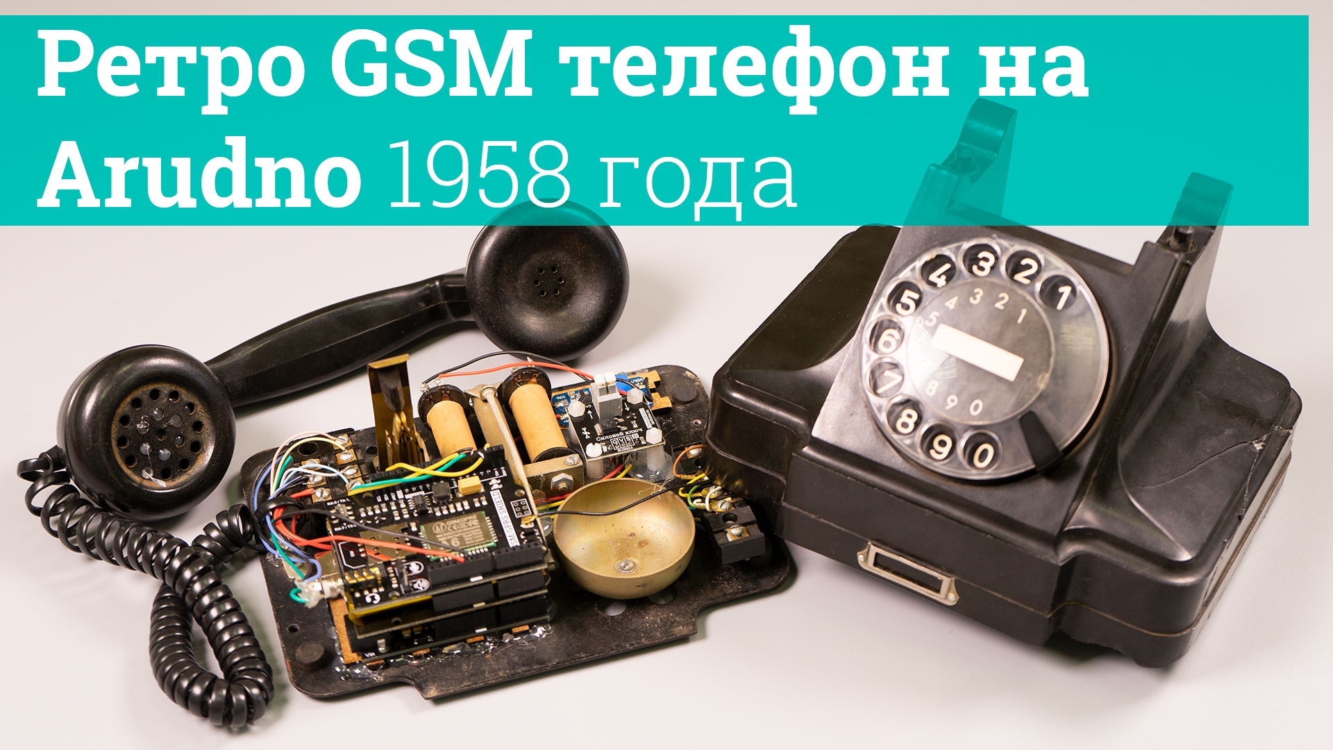
В этом уроке мы дадим вторую жизнь телефонному аппарату с дисковым номеронабирателем, превратив его в мобильный (переносной) ретро-аппарат сотовой связи.
Есть стационарные телефонные аппараты у которых нет провода между трубкой и базой, но есть провод к розетке АТС. В нашем проекте у телефона останется провод между трубкой и базой, но пропадёт провод к розетке, так как связь будет осуществляться по сети GSM.
Описание работы ретро GSM телефона:
- После подачи питания дождитесь кратковременного колокольного звонка, он оповещает о том, что модем GSM зарегистрирован в сети сотового оператора связи.
- Телефон может принимать входящие звонки если трубка лежит на телефоне.
- Можно снять трубку (при отсутствии входящего звонка) для перехода в режим «я занят».
- Для ответа на входящий звонок нужно поднять трубку.
- Для завершения разговора нужно положить трубку на телефон.
- Набираемый номер должен состоять из 11 цифр и начинаться с цифры 7 или 8.
- Можно набирать номера 01, 02, 03, 04, 100, предварительно указав код города 8(495).
- Можно набирать номера 101, 102, 103, 104, 112.
- Ввод цифр номера осуществляется поворотом заводного диска до нужной цифры с последующим самовозвратом диска в исходное положение.
- Для совершения исходящего вызова выполните следующие действия:
- Поднимите трубку при отсутствии входящего вызова.
- Дождитесь появления гудка в трубке, он сигнализирует о наличии связи с сотовым оператором, следовательно, готовности к набору номера.
- Наберите номер вызываемого абонента.
- Если Вы ошиблись, опустите, поднимите трубку и повторите набор заново.
- Во время набора номера гудок в трубке должен пропасть. Вместо него, во время возврата заводного диска, имитируется звук «щелчков» от набора номера.
- После ввода последней (одиннадцатой) цифры номера дождитель появления сигнала вызова (длинные гудки или мелодия), или сигнала занят (короткие гудки).
- Если абонент ответит на Ваш вызов, то установится голосовое соединение.
- Если абонент разорвёт голосовую связь, Вы услышите сигнал занят (короткие гудки).
- Завершить вызов, набор, соединение или разговор можно в любое время повесив трубку.
- Динамик в телефонной трубке излучает звуки разговора и сигнал вызова (длинные гудки или мелодия), а все остальные сигналы формируются звукоизлучателем (зуммером), так же установленным в телефонную трубку.
Нам понадобится:
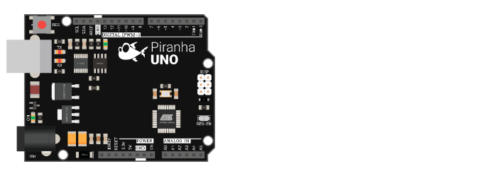
- Arduino / Piranha UNO.
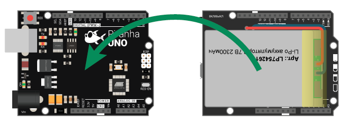
- GSM/GPRS Shield A6.
- Battery Shield.
- Звук разговора и сигналов (можно выбрать один из вариантов):
- Динамик + микрофон + зуммер с генератором (в корпусе трубки телефона).
- Гарнитура с микрофоном + Trema зуммер с генератором.
- Колокольный звонок (можно выбрать один из вариантов):
- Колокольный звонок телефона + Trema силовой ключ + повышающий DC-DC преобразователь.
- Звонок из соленоида + колокол + Trema силовой ключ + повышающий DC-DC преобразователь.
- Звонок из сервопривода + колокол.
- Дисковый номеронабиратель (если его нет в корпусе телефона).
- Трема кнопка (если в корпусе телефона нет кнопки опускания трубки).
- Корпус телефона.
- Для реализации проекта нам необходимо установить библиотеку:
- iarduino_GSM.
- Библиотеки SoftwareSerial и Servo входят в стандартный набор Arduino IDE.
О том как устанавливать библиотеки, Вы можете ознакомиться на странице Wiki — Установка библиотек в Arduino IDE.
Схема сборки:
Arduino / Piranha UNO:
Если Вы собираетесь разместить устройство в корпусе телефона, найдите место для установки Arduino / Piranha UNO и закрепите её.
Batery Shield:
Установите Battery Shield на Arduino / Piranha UNO:
Во время установки Battery Shield должен быть в выключенном состоянии.
GSM/GPRS Shield:
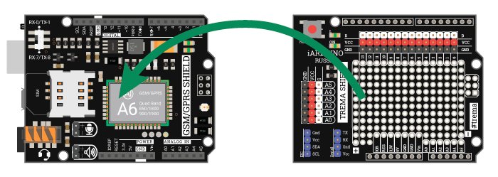
На Battery Shield установите GSM/GPRS Shield A6:
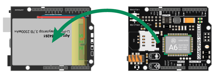
На плате GSM/GPRS Shield A6 имеется слот для SIM-карт и переключатель UART. Установите SIM-карту в слот, выберите положение переключателя RX-7/TX-8.
Trema Shield:
На GSM/GPRS Shield A6 установите Trema Shield:
Номеронабиратель:
Подключите номеронабиратель к выводам GND, D5, D6 и Трема кнопку к выводу D4:
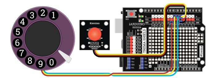
Если Вы собираете устройство в корпусе телефона, то вместо Trema кнопки подключите кнопку фиксации опускания трубки, между выводами GND и D4).
Колокольный звонок:
Подключите модули управления колокольным звонком:

Напряжение питания 5В подводится на вход повышающего DC-DC преобразователя, а напряжение с его выхода (уровень напряжения регулируется потенциометром преобразователя) подводится к соленоиду или родной катушке звонка телефона, через Trema силовой ключ, управление которым осуществляется через вывод D2.
Колокольный звонок можно собрать не на соленоиде, а на сервоприводе, подключив его к выводу D2:
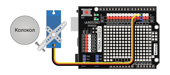
Преимуществом данной схемы является меньшее число деталей. Но в скетче нужно присвоить переменной modeBEEL значение 2 (разкомментировать строку в начале скетча), а так же указать углы сервопривода при которых боёк касается колокола и удаляется от него (углы указываются в функции funcBELL в конце скетча).
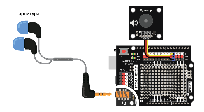
Устройство ввода/вывода звука:
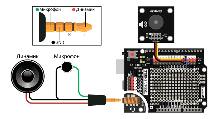
Если Вы собираетесь разместить динамик, микрофон и зуммер в трубке телефона, то подключите их согласно схеме: (трубка соединяется с аппаратом четырехпроводным кабелем).
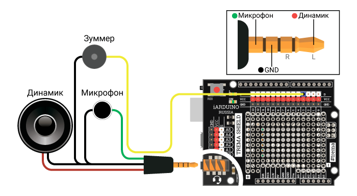
В телефонной трубке, рядом с динамиком, необходимо разместить и зуммер. Он подключается к выводу D3 и нужен для подачи сигналов «готов к набору» (гудок при снятой трубке) и «занято» (прерывистые гудки после разрыва голосового соединения).
Если Вы не собираетесь размещать элементы ввода/вывода звука в телефонной трубке, то более простым вариантом является использование гарнитуры, которая подключается к соответствующему разъёму на плате GSM/GPRS Shield A6, а сигналы «готов к набору» и «занято» будут выводиться отдельно, через Trema зуммер, так же подключённый к выводу D3.
Если Вы не собираетесь размещать элементы ввода/вывода звука в телефонной трубке, но и не желаете использовать гарнитуру, то реализуйте вот такую схему:
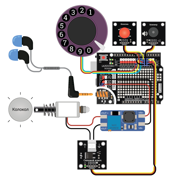
Полная схема устройства:
Пример схемы с использованием гарнитуры и колокольного звонка на базе соленоида:
Код программы (скетч):
В скетче предусмотрена возможность выбора типа колокольного звонка modeBEEL=0,1,2 и алгоритма работы кнопки фиксирующей опускание телефонной трубки flgHANG=0,1. Для выбора необходимого значения закомментируёте существующее и разкомментируйте требуемое.
В скетче используются библиотеки iarduino_GSM, SoftwareSerial и Servo (две последние входят в стандартный набор Arduino IDE).
// Телефонный аппарат с импульсным номеронабирателем на базе GSM/GPRS Shield A6
// ============================================================================
//
// Определяем номера выводов: //
uint8_t pinBELL = 2; // Вывод (выход) используемый для подключения силового ключа (для включения звонка вызова).
uint8_t pinBEEP = 3; // Вывод (выход) используемый для подключения излучателя звука (для вывода гудков в трубке).
uint8_t pinHANG = 4; // Вывод (вход) используемый для подключения кнопки (NC) фиксирующей опускание телефонной трубки.
uint8_t pinDIAL = 5; // Вывод (вход) используемый для подключения шунтирующего контакта (NO) номеронабирателя.
uint8_t pinPULSE = 6; // Вывод (вход) используемый для подключения тактирующего контакта (NC) номеронабирателя.
uint8_t pinRX = 7; // Вывод (вход) используемый как линия RX (приём ) программной шины UART (данные от GSM/GPRS Shield к Arduino).
uint8_t pinTX = 8; // Вывод (выход) используемый как линия TX (передача) программной шины UART (данные к GSM/GPRS Shield от Arduino).
//
// Определяем тип колокольного звонка: //
uint8_t modeBEEL = 0; // Колокольный звонок собран на соленоиде (электромагнитной катушке, собственном звонке телефона).
// uint8_t modeBEEL = 1; // Колокольный звонок собран на электромоторе с бойком закреплённым к его ротору.
// uint8_t modeBEEL = 2; // Колокольный звонок собран на сервоприводе с бойком закреплённым к его качалке.
//
// Определяем алгоритм работы кнопки: //
bool flgHANG = 0; // 0-(NC) контакты кнопки замкнуты при лежащей трубке.
// bool flgHANG = 1; // 1-(NO) контакты кнопки разомкнуты при лежащей трубке.
//
// Объявляем переменные и функции: //
bool flgPowerON = true; // Определяем флаг подачи питания.
uint8_t cntPULSE; // Объявляем переменную для подсчёта импульсов в последней набранной цифре (10 импульсов для цифры 0).
uint8_t cntDigits; // Объявляем переменную для подсчёта набранных цифр номера.
char strNumber[12]; // Объявляем строку для хранения номера вызываемого/вызывающего телефона (11 символов номера + символ конца строки).
void funcBELL(bool); // Объявляем функцию управления звонком (true - подаёт один колокольный звон, false - выключает колокольный звонок).
//
// Подключаем библиотеки: //
#include <iarduino_GSM.h> // Подключаем библиотеку iarduino_GSM для работы с GSM/GPRS Shield.
#include <SoftwareSerial.h> // Подключаем библиотеку SoftwareSerial для программной реализации шины UART.
#include <Servo.h> // Подключаем библиотеку Servo для работы с сервоприводом (если колокольный звонок собран на сервоприводе).
//
// Создаём объекты: //
iarduino_GSM gsm; // Создаём объект gsm для работы с функциями и методами библиотеки iarduino_GSM.
SoftwareSerial softSerial(pinRX, pinTX); // Создаём объект softSerial указывая выводы платы Arduino используемые в качестве линий RX и TX программной шины UART.
Servo srv; // Создаём объект srv для работы с функциями и методами библиотеки Servo (если колокольный звонок собран на сервоприводе).
//
void setup(){ //
Serial.begin(9600); // █ Инициируем связь с монитором последовательного порта на скорости 9600 бит/сек.
if(modeBEEL==2){srv.attach(pinBELL);} // Назначаем объекту srv управление сервоприводом подключённым к выводу pinBELL (если колокольный звонок собран на сервоприводе).
else{pinMode(pinBELL,OUTPUT); digitalWrite(pinBELL,LOW);} // Переводим вывод pinBELL в режим выхода и устанавливаем на нём уровень логического «0» (если колокольный звонок собран на соленоиде/электромагните/электромоторе).
pinMode(pinBEEP, OUTPUT); digitalWrite(pinBEEP, LOW ); // Переводим вывод pinBEEP в режим выхода и устанавливаем на нём уровень логического «0».
pinMode(pinHANG, INPUT ); digitalWrite(pinHANG, HIGH); // Переводим вывод pinHANG в режим входа и подтягиваем его к Vcc.
pinMode(pinDIAL, INPUT ); digitalWrite(pinDIAL, HIGH); // Переводим вывод pinDIAL в режим входа и подтягиваем его к Vcc.
pinMode(pinPULSE, INPUT ); digitalWrite(pinPULSE, HIGH); // Переводим вывод pinPULSE в режим входа и подтягиваем его к Vcc.
//
funcBELL(false); // Отключаем колокольный звонок входящего вызова.
gsm.begin(softSerial); // Инициируем работу GSM/GPRS Shield, указывая объект (или класс) для работы с её шиной UART.
//
// Ждём готовность GSM/GPRS Shield к работе: //
while(gsm.status()!=GSM_OK){delay(1000);} // Ждём завершения регистрации модема в сети оператора связи.
//
// Переводим звук на гарнитуру (к ней подключена трубка): //
gsm.SOUNDdevice(GSM_HEADSET); // Для громкой связи нужно вместо GSM_HEADSET указать GSM_SPEAKER.
//
// Информируем о готовности модуля кратковременным включением колокольного звонка: //
if(flgPowerON){ //
// Если функция setup() выполняется в первый раз: //
uint32_t i = millis() + 1000; // Определяем длительность звонка готовности модуля.
while(i>millis()){ funcBELL(true); } funcBELL(false); // Включаем и отключаем колокольный звонок.
flgPowerON = false; // Сбрасываем флаг подачи питания.
} //
Serial.println(F("Готов к работе!")); // █ Можно добавить код выполняемый однократно после готовности аппарата при подаче питания.
} //
//
void loop (){ //
/******* СОВЕРШАЕМ ИСХОДЯЩИЙ ЗВОНОК *******/ // Для исходящего звонка нужно поднять трубку и набрать номер.
if(digitalRead(pinHANG)^flgHANG){ // Если на входе pinHANG установлена логическая «1» (трубка снята).
// Если трубка снята: //
delay(100); // Подавляем дребезг поднятия трубки.
// Готовимся к набору номера: //
cntDigits = 0; // Сбрасываем счетчик набранных цифр номера (номер ещё не набирался).
strNumber[0]=''; // Чистим строку набираемого номера.
digitalWrite(pinBEEP, LOW); // Отключаем тоновый сигнал в трубке телефона (если он был включён).
Serial.println(F("Трубка снята, проверяем готовность к набору номера ...")); // █ Можно добавить код выполняемый однократно при поднятии трубки для набора номера, до проверки наличия связи с оператором.
// Проверяем готовность GSM/GPRS Shield к работе: //
if(gsm.status()!=GSM_OK){ //
// Если модуль не готов к работе (например, ошибка регистрации в сети): //
Serial.println(F("Перезагрузка модуля")); // █ Выводим сообщение о перезагрузке модуля.
// Заново инициируем работу с модулем: //
setup(); //
} //
// Информируем о готовности к набору номера: //
digitalWrite(pinBEEP, HIGH); // Включаем тоновый сигнал в трубке телефона (оповещая о готовности к набору номера).
Serial.println(F("Можно набирать номер ...")); // █ Можно добавить код выполняемый однократно при поднятии трубки для набора номера, после проверки связи с оператором.
while(digitalRead(pinHANG)^flgHANG){ // Входим в цикл, который будет завершён опусканием трубки на телефон.
// Цикл выполняется всё время, пока снята трубка: //
if(!digitalRead(pinDIAL)){ // Если шунтирующая контактная группа номеронабирателя замкнулась (значат набор цифры), то ...
// Если начинается набор очередной цифры номера: //
delay(20); // Подавляем дребезг шунтирующей контактной группы номеронабирателя.
digitalWrite(pinBEEP, LOW); // Отключаем тоновый сигнал в трубке телефона (если он был включён).
cntPULSE=0; // Сбрасываем счётчик поступивших импульсов от номеронабирателя.
Serial.print(F("Набирается цифра ... ")); // █ Можно добавить код выполняемый однократно перед набором каждой цифры номера
while(!digitalRead(pinDIAL) && (digitalRead(pinHANG)^flgHANG)){ // Если чтение импульсов набираемой цифры разрешено (шунтирующие контакты номеронабирателя замкнуты) и трубка снята, то ...
// Цикл выполняется пока набирается очередная цифра номера: //
if(digitalRead(pinPULSE)){ // Если поступил тактирующий импульс (импульсная контактная группа номеронабирателя разомкнулась), то ...
// Фронт импульса: //
digitalWrite(pinBEEP, HIGH); // Включаем тоновый сигнал в трубке телефона.
delay(5); // Подавляем дребезг импульсной контактной группы номеронабирателя.
digitalWrite(pinBEEP, LOW); // Отключаем тоновый сигнал в трубке телефона.
while(digitalRead(pinPULSE) && (digitalRead(pinHANG)^flgHANG)){delay(5);} // Ждём завершения тактирующего импульса (замыкания импульсной контактной группы номеронабирателя) или опускания трубки.
// Спад импульса: //
delay(5); // Подавляем дребезг импульскной контактной группы номеронабирателя.
cntPULSE++; // Увеличиваем счётчик полученных импульсов.
} //
} //
delay(20); // Подавляем дребезг шунтирующей контактной группы номеронабирателя.
// Очередная цифра номера набрана: //
if(cntPULSE){ // Если от импульсной контактной группы номеронабирателя поступил хотя бы 1 импульс, то ...
// Если цифра набрана корректно (во время набора поступил хотя бы один импульс) //
if(cntPULSE>=10){cntPULSE=0;} // Если поступило 10 импульсов, значит набрана цифра 0.
strNumber[cntDigits]=cntPULSE+48; // Сохраняем код набранной цифры в строку с набираемым номером.
cntDigits++; // Переходим к следующей цифре набираемого номера.
strNumber[cntDigits]=''; // Сохраняем код конца строки.
Serial.println(cntPULSE); // █ Можно добавить код выполняемый однократно после набора каждой цифры номера.
} //
// Проверяем введённые цифры номера: //
if( cntDigits==11 // Если набрано 11 цифр номера *(***)***-**-** - обычный номер.
|| (cntDigits==7 && strncmp("8495100", strNumber, 8)==0) // Если набрано 7 цифр номера 8(495)100 - точное время (городской).
|| (cntDigits==6 && strncmp("849501", strNumber, 7)==0) // Если набрано 6 цифр номера 8(495)01 - пожарная служба (городской).
|| (cntDigits==6 && strncmp("849502", strNumber, 7)==0) // Если набрано 6 цифр номера 8(495)02 - полиция (городской).
|| (cntDigits==6 && strncmp("849503", strNumber, 7)==0) // Если набрано 6 цифр номера 8(495)03 - скорая помощь (городской).
|| (cntDigits==6 && strncmp("849504", strNumber, 7)==0) // Если набрано 6 цифр номера 8(495)04 - газовая служба (городской).
|| (cntDigits==3 && strncmp("101", strNumber, 4)==0) // Если набрано 3 цифры номера 101 - пожарная служба.
|| (cntDigits==3 && strncmp("102", strNumber, 4)==0) // Если набрано 3 цифры номера 102 - полиция.
|| (cntDigits==3 && strncmp("103", strNumber, 4)==0) // Если набрано 3 цифры номера 103 - скорая помощь.
|| (cntDigits==3 && strncmp("104", strNumber, 4)==0) // Если набрано 3 цифры номера 104 - газовая служба.
|| (cntDigits==3 && strncmp("112", strNumber, 4)==0) // Если набрано 3 цифры номера 112 - экстренные оперативные службы.
){ //
// Если номер набран полностью, то инициируем вызов ... //
if(gsm.CALLdial(strNumber)){ // Инициируем исходящий голосовой вызов на номер указанный в строке strNumber.
// Если исходящий вызов инициирован, ждём завершения набора номера ... //
Serial.println((String) "Набор номера " + strNumber + " ..."); // █ Можно добавить код выполняемый однократно при начале набора номера.
while(gsm.CALLstatus()==GSM_CALL_OUT_DIAL && (digitalRead(pinHANG)^flgHANG)){} // Цикл выполняется пока установлено состояние вызова "набирается номер" и снята трубка.
while(gsm.CALLstatus()==GSM_CALL_OUT_DIAL && (digitalRead(pinHANG)^flgHANG)){} // Повторяем цикл на случай кратковременного изменения статуса вызова.
while(gsm.CALLstatus()==GSM_CALL_OUT_DIAL && (digitalRead(pinHANG)^flgHANG)){} // Повторяем цикл на случай кратковременного изменения статуса вызова.
if(gsm.CALLstatus()==GSM_OK){ //
// Если произошёл обрыв связи с оператором: //
Serial.println(F("произошёл обрыв связи с оператором.")); // █ Можно добавить код выполняемый однократно при обрыве связи с оператором.
} //
if(gsm.CALLstatus()==GSM_CALL_OUT_BEEP){ // Если установилось состояние вызова "дозвон", то ...
// Если начался дозвон, то ждём пока вызываемый абонент не ответит ... //
Serial.println(F("Ожидание ответа ...")); // █ Можно добавить код выполняемый однократно при поступлении гудков у вызываемого абонента.
while(gsm.CALLstatus()==GSM_CALL_OUT_BEEP && (digitalRead(pinHANG)^flgHANG)){} // Цикл выполняется пока установлено состояние вызова "дозвон" и снята трубка.
delay(500); // Даём время для установки состояния вызова - "соединён".
} //
if(gsm.CALLstatus()==GSM_CALL_ACTIVE){ // Если установилось состояние вызова "соединён", то ...
// Если установлено активное голосовое соединение ... //
Serial.println(F("Исходящее голосовое соединение установлено.")); // █ Можно добавить код выполняемый однократно при установлении активного голосового соединения.
while(gsm.CALLstatus()==GSM_CALL_ACTIVE && (digitalRead(pinHANG)^flgHANG)){} // Цикл выполняется пока установлено активное голосовое соединение и снята трубка.
// Если голосовое соединение разорвано или его требуется разорвать ... //
} //
Serial.println(F("Разговор завершён.")); // █ Можно добавить код выполняемый однократно в момент завершения разговора.
} //
// Разрываем голосовое соединение, если разговор завершён опусканием трубки: //
gsm.CALLend(); // Разъединяем голосовое соединение.
// Выводим короткие звуковые сигналы в трубку телефона... //
while(digitalRead(pinHANG)^flgHANG){ // Цикл выполняется пока снята трубка.
if(millis()%1000<500){digitalWrite(pinBEEP, HIGH);} // Выводим тоновый сигнал в трубке телефона в течении первых 500 мс каждых 1000 мс.
else {digitalWrite(pinBEEP, LOW );} // Отключаем тоновый сигнал в трубке телефона в течении остального времени из 1000 мс.
} digitalWrite(pinBEEP, LOW ); // Отключаем тоновый сигнал в трубке телефона.
} //
} //
gsm.CALLend(); // Разъединяем голосовое соединение, если нам позвонили пока поднята трубка (до или в момент набора номера).
} //
Serial.println(F("Трубка опущена на аппарат.")); // █ Можно добавить код выполняемый однократно в момент опускания трубки на аппарат.
}else{ //
/******* ПРИНИМАЕМ ВХОДЯЩИЙ ЗВОНОК *******/ // Для приёма входящих звонков трубка должна быть опущена.
// Если трубка лежит на телефоне: //
delay(100); // Подавляем дребезг опускания трубки.
digitalWrite(pinBEEP, LOW); // Отключаем тоновый сигнал в трубке телефона (если он был включён).
Serial.println(F("Трубка лежит на аппарате, режим ожидания звонка ...")); // █ Можно добавить код выполняемый однократно в момент перехода в режим ожидания входящего звонка
while(!digitalRead(pinHANG)^flgHANG){ // Входим в цикл, который будет завершён поднятием трубки с телефона.
// Цикл выполняется всё время, пока трубка не поднята: //
if(gsm.CALLavailable(strNumber)){ // Функция CALLavailable() возвращает true если есть входящий дозванивающийся вызов, номер вызывающего абонента сохраняется в строку strNumber.
// Если есть входящий вызов в режиме дозвона, то ждём ответа поднятием трубки ... //
Serial.println((String)"Входящий вызов "+strNumber+", ждём поднятия трубки ..."); // █ Можно добавить код выполняемый однократно в момент поступления входящего звонка
while(gsm.CALLavailable() && !(digitalRead(pinHANG)^flgHANG)){ // Цикл выполняется пока есть входящий вызов в режиме дозвона и трубка не поднята.
// Информируем колокольными звонками о наличии входящего вызова: //
while(millis()%4000<2000){funcBELL(true);} // Включаем колокольный звонок в течении первых 2000 мс каждых 4000 мс.
funcBELL(false); // Отключаем колокольный звонок в течении остального времени.
} //
delay(100); // Подавляем дребезг поднятия трубки.
// Проверяем почему был завершён цикл ожидания ответа ... //
if(digitalRead(pinHANG)^flgHANG){ // Если трубка снята.
// Если цикл завершён по причине поднятия трубки: //
Serial.println(F("Трубка снята, отвечаем на звонок")); // █ Можно добавить код выполняемый однократно в момент поднятия трубки для ответа на входящий звонок.
if(gsm.CALLavailable()){ // Функция CALLavailable() возвращает true если есть входящий дозванивающийся вызов.
// Если вызывающий абонент всё ещё ждёт ответа (поднятия трубки) ... //
gsm.CALLup(); // Отвечаем на вызов.
// Ждём пока состояние вызова "дозвон" не сменится ... //
while(gsm.CALLstatus()==GSM_CALL_IN_BEEP){;} // Функция CALLstatus() возвращает статус текущего голосового вызова, значение GSM_CALL_IN_BEEP указывает на наличие входящего дозванивающегося вызова.
if(gsm.CALLstatus()==GSM_CALL_ACTIVE){ // Функция CALLstatus() возвращает статус текущего голосового вызова, значение GSM_CALL_ACTIVE указывает на наличие активного голосового соединения.
// Если установлено активное голосовое соединение ... //
Serial.println(F("Входящее голосовое соединение установлено.")); // █ Можно добавить код выполняемый однократно при установлении активного голосового соединения.
while(gsm.CALLstatus()==GSM_CALL_ACTIVE && (digitalRead(pinHANG)^flgHANG)){} // Цикл выполняется пока установлено активное голосовое соединение и снята трубка.
} //
// Если голосовое соединение разорвано или требуется разорвать ... //
Serial.println(F("Разговор завершён.")); // █ Можно добавить код выполняемый однократно в момент завершения разговора.
// Разрываем голосовое соединение, если разговор завершён опусканием трубки: //
gsm.CALLend(); // Разъединяем голосовое соединение, это требуется если мы инициировали разрыв соединения опусканием трубки.
} //
// Выводим короткие звуковые сигналы в трубку телефона... //
while(digitalRead(pinHANG)^flgHANG){ // Цикл выполняется пока снята трубка.
if(millis()%1000<500){digitalWrite(pinBEEP, HIGH);} // Выводим тоновый сигнал в трубке телефона в течении первых 500 мс каждых 1000 мс.
else {digitalWrite(pinBEEP, LOW );} // Отключаем тоновый сигнал в трубке телефона в течении остального времени из 1000 мс.
} digitalWrite(pinBEEP, LOW ); // Отключаем тоновый сигнал в трубке телефона.
}else{ //
// Если цикл завершён по причине сброса вызова: //
Serial.println(F("Вызов завершён по причине сброса вызова")); // █ Можно добавить код выполняемый однократно в момент сброва вызова.
} //
}else{ //
// Если входящих вызовов в режиме дозвона нет: //
if(gsm.status()!=GSM_OK){ //
// Если модуль не готов к работе (например, ошибка регистрации в сети): //
Serial.println(F("Перезагрузка модуля")); // █ Выводим сообщение о перезагрузке модуля.
// Заново инициируем работу с модулем: //
setup(); //
} //
} //
} //
} //
} //
//
// Функция управления колокольным звонком: // В зависимости от параметра (f) функция либо отключает колокольный звонок, либо подаёт один колокольный звон входящего вызова.
void funcBELL(bool f){ // В данной функции можно регулировать тональность колокольного звонка, меняя задержку delay().
if(modeBEEL==0){ //
// Если колокольный звонок собран на соленоиде (электромагнитной катушке): //
if(f){digitalWrite(pinBELL, HIGH); delay(20); // Если установлен флаг f, то: - подаём высокий уровень на выход pinBELL (силовой ключ замкнётся , через катушку потечёт ток и боёк ударит о колокол), ждём 20 мс.
digitalWrite(pinBELL, LOW ); delay(20); // - подаём низкий уровень на выход pinBELL (силовой ключ разомкнётся, катушка будет обесточена и боёк удалится от колокола), ждём 20 мс.
}else{digitalWrite(pinBELL, LOW );} // Если сброшен флаг f, то - подаём низкий уровень на выход pinBELL (силовой ключ разомкнётся, катушка будет обесточена и боёк удалится от колокола).
}else if(modeBEEL==1){ //
// Если колокольный звонок собран на электромоторе: //
if(f){digitalWrite(pinBELL, HIGH);} // Если установлен флаг f, то - подаём высокий уровень на выход pinBELL (силовой ключ замкнётся , электромотор включится и боёк на его роторе начнёт бить по колоколу).
else {digitalWrite(pinBELL, LOW );} // Если сброшен флаг f, то - подаём низкий уровень на выход pinBELL (силовой ключ разомкнётся, электромотор отключится и боёк перестанет бить по колоколу).
}else if(modeBEEL==2){ //
// Если колокольный звонок собран на сервоприводе: //
if(f){srv.write(50); delay(20); // Если установлен флаг f, то: - поворачиваем сервопривод на угол при котором боёк закреплённый к его качалке ударит о колокол, ждём 20 мс.
srv.write(60); delay(20); // - поворачиваем сервопривод на угол при котором боёк закреплённый к его качалке удалится от колокола, ждём 20 мс.
}else{srv.write(60);} // Если сброшен флаг f, то - поворачиваем сервопривод на угол при котором боёк закреплённый к его качалке удалится от колокола.
} // Вместо углов 50° и 60° необходимо указать Ваши углы (значение подбирается экспериментально).
} //
В разделе функции funcBELL отвечающем за управление сервоприводом указаны углы 50° и 60° (три последние строки). Если Вы используете колокольный звонок на сервоприводе, измените угол 50° на тот при котором сервопривод ударяет бойком по колоколу, а угол 60° на тот при котором боёк удаляется от него.
Алгоритм работы скетча:
До кода Setup() определяются номера выводов, тип колокольного звонка, алгоритм работы кнопки фиксирующей опускание трубки, объявляются переменные и функции, подключаются библиотеки, и создаются объекты для работы с ними.
В коде setup() конфигурируются выбранные выводы, инициируется работа GSM/GPRS Shield, звук переводится на разъём гарнитуры, выполняется цикл ожидания готовности GSM/GPRS Shield к работе (регистрация в сети оператора). И после выполнения всех указанных действий выполняется оповещение о готовности к работе, путем включения колокольного звонка на 1 секунду.
Код цикла loop() разделён на две основные части: совершение исходящих звонков (данная часть выполняется если телефонная трубка снята) и приём входящих вызовов (данная часть выполняется если трубка лежит на телефоне).
Совершение исходящих звонков состоит из следующих действий:
- Обнуление переменных, проверка связи с оператором, вывод сигнала в трубку телефона о готовности к работе.
- Дальнейшие действия происходят в отдельном цикле, выход из которого возможен только если положить трубку на телефон. Так же в этом цикле постоянно сбрасывается голосовое соединение, не давая другим абонентам позвонить нам при снятой трубке.
- Если начинается набор номера, то отключаем сигнал в телефонной трубке, подсчитываем количество импульсов набираемых цифр. После каждой введённой цифры из значение добавляется в строку с номером, которая проверяется на корректность (достижение 11 знаков, или совпадение с коротким номером). При желании Вы можете добавить или удалить некоторые короткие номера из скетча.
- Если номер в строке корректен, то производится его набор, с дальнейшей проверкой состояния связи. Если связь установлена, то выполняется пустой цикл ожидания её разрыва.
- При разрыве голосового соединения выполняется цикл вывода коротких звуковых сигналов в телефонную трубку. Этот цикл выполняется постоянно, пока не положить трубку на телефон.
Приём входящих вызовов состоит из следующих действий:
- Отключение тонального сигнала в телефонной трубке (на случай если он был).
- Дальнейшие действия происходят в отдельном цикле, выход из которого возможен только если снять трубку с телефона при отсутствии входящего вызова.
- Если зафиксирован входящий вызов, то выполняется цикл включающий колокольный звонок, пока входящий вызов не изменит свой статус или не будет поднята трубка.
- Если статус вызова изменился по причине поднятия трубки, то устанавливается голосовое соединение, и выполняется пустой цикл ожидания разрыва этого соединения.
- После разрыва голосового соединения выполняется цикл вывода коротких звуковых сигналов в телефонную трубку. Этот цикл выполняется постоянно, пока не положить трубку на телефон.
В конце скетча определена функция управления колокольным звонком. Данная функция принимает один параметр типа bool (true — ударить в колокол и освободить его / false — освободить колокол). В зависимости от значения переменной modeBEEL функция работает с колокольными звонками собранными на базе соленоида, родного звонка телефона, сервопривода или электромотора.
Ссылки:
- Библиотека iarduino_GSM.
- Arduino / Piranha UNO.
- GSM/GPRS Shield A6.
- Wiki — GSM/GPRS Shield A6.
- Battery Shield.
- Wiki — Battery Shield.
- Динамик.
- Микрофон.
- Зуммер с генератором.
- Trema силовой ключ.
- Повышающий DC-DC преобразователь
- Соленоид.
- Сервопривода.
- Дисковый номеронабиратель.
- Трема кнопка.
Говорите, задолбали обзоры часов на сайте? Ну так держите ещё один обзор по теме Arduino 
В комментариях к предыдущему обзору кто-то ворчал, что, мол, «купи Arduino и затем готовься выложить ещё баксов двести на дополнения, когда интерес проснётся». Незвестный собрат — ты был прав
Итого, герой обзора — нахлобучка (или «shield») для Arduino с GSM/GPRS модулем на борту. Вся идея Arduino состоит в том, что размеры плат и контакты — стандартные и изделия разных производителей можно стыковать меж собой.
Вставляем SIM-карту в держалку хлипковатого вида:
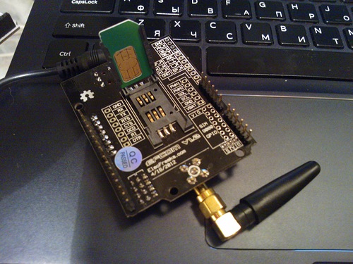
затем втыкаем shield на Arduino UNO — встаёт, как влитой:
Подключаем к shield комплектный блок питания на 9 вольт и 1А (к сожалению, идёт с американской вилкой, т.е. нужен переходник), подцеляем этот «бутерброд» к компьютеру. Светодиод на корпусе начинает мигать, через секунд десять SIM-карта регистрируется в сети и мигания становятся редкими.
Но мы не светодиод за 57 баксов разглядывать собирались; руки чешутся сделать что-нибудь прикольное. Сначала попробуем проверить работоспособность модуля. С внешним миром он общается через последовательный порт, так что по инструкции с сайта производителя запихиваем в Arduino с компьютера простую программку, которая будет выступать мостом между компьютером и GSM-модулем. Arduino будет передавать туда команды как есть и возвращать в компьютер ответы.
Копируем программу, компилируем, запихиваем в Arduino, открываем Serial monitor. Не работает. Чертыхаемся, идём читать инструкцию, бъём себя по лбу, выставляем рекомендованные — скорость порта в 19200 байт в секунду, символ конца строки — CR. Перезапускаем.
Вводим в окно Serial monitor стандартную «модемную» команду «AT» и в ответ получаем «OK». Ааааа, оно работает!!! Набираем вручную зубодробительную команду отправки SMS — отправляет!
Лезем на Google Code и скачиваем библиотеку, написанную яйцеголовыми умниками под эту железку, распаковываем и открываем пример с тестом GPRS-соединения.
В примере прописываем МегаФоновскую точку доступа GPRS, поправив единственную строчку
inet.attachGPRS("internet", "gdata", "gdata")и запускаем. Через секунд двадцать Arduino заходит в интернет по GPRS и показывает нам содержимое одной из страниц Яндекса:
Надо отметить, что всё это добро занимает только 11 килобайт памяти Arduino, т.е. ещё остаётся приличный запас для других полезных задач.
Итак, что мы имеем:
— относительно недорогую штуку, с помощью которой можно управлять Arduino по SMS. Например, хотите включать бойлер на даче, пока ещё стоите в пятничной пробке? Подключайте к Arduino нормальные, качественные реле, закодируйте в программе пароль, чтобы шальная рекламная SMS не включила ваш котёл — и будете каждый раз к приезду иметь нагретую воду для душа.
— возможность собирать данные с Arduino не с помощью дорогих SMS, а через Web. Лично я буду собирать OBD-II + GPS логгер для машины, который будет складывать данные о пробеге мне на домашний компьютер.
Несколько впечатлений по самой железке. Плюсы:
— добротная пайка
— можно поставить более крутую антенну (винтовое SMA-соединение позволяет)
— на плате есть встроенные часы и конденсатор, который их питает
— есть коннектор для «нокиевского» LCD-экранчика
— используется чип Simcom SIM900, на который в интернетах полно документации.
— комплект приехал в крепкой картонной коробке.
— есть гнёзда для наушников и микрофона (не тестировал).
Минусы:
— хлипковатый слот для SIM-карты
— нет 3G, только четырёхдиапазонный GSM/GPRS
— для работы требуется внешнее питание 9 вольт, питания от USB не хватает
— стали появляться в продаже модули с чипом следующего поколения, SIM908, в который уместили заодно GPS-приёмник. Скоро они подешевеют, а я буду локти кусать 
— библиотеки расчитаны на Arduino UNO или Mega, если у вас, например, Leonardo, то могут быть проблемы.
— в комплекте БП с американской вилкой, нужен переходник.
Introduction: Arduino MobilePhone
Actually there are no real reasons why one should build a (mobile-)phone by himself. Especially as the simplest phone costs actually less than doing it yourself. Nevertheless, learning is very important aspect of the assembly process. Furthermore, walking around with a self-built phone sounds just very awesome idea.
Most of us have our own mobile phone, so do I. After building the T-gameBoY I was looking new challenges and thought I should make myself a phone. Clearly I’m not able to achieve the smartphone functionality, but calling and maybe additionally sending SMS-s would be good enough.
Step 1: Planning
With Google search I found perfectly suitable example from Matt Richardson (MR). His design is very nice and interesting, additionally he mentioned few possible problem areas.
- His design in Instructables
- Another
Next to his design are two alternatives from Adafruit.com. One uses a Raspberry Pi and the second one an Arduino as the bases. The phone unit itself is the same for both. Adafruit design is simple to build and looks very attractive with the touch screen. Nevertheless, there is almost nothing to do with building. It’s more about buying the components and then fast assembly. This sounded too simple for me.
- Raspberry phone
- Arduino phone
Enough about that and let’s focus on the device itself. I used MR design as an inspiration and focused on the Adafruit Arduino model.
GSM cellular module
The most important component, the GSM cellular module, the one used by MR is difficult to acquire and expensive. The Adafruit design uses an alternative module (SIM800L) and I was looking what I could do with that. Soon I found that I could buy this module from eBay with very reasonable price without having to do almost any soldering. My aim was not avoiding soldering, but to reduce the time consuming soldering work.
Adafruit uses the same SIM800L chip and later for my surprise I was able to use their code directly without any modifications.
- Adafruit FONA
The module works in 850/900/1800/1900MHz systems, allows FM radio and much more. The radio was not important for me, but maybe in the future I could make use from that. Important features as calling, receiving and sending SMS are covered, that’s actually enough.
As an extra bonus the bought module had already an antenna included. On the other side of the module board is a SIM card slot, making again my life easier (reducing the small and time consuming soldering work).
Speaker “+” (SpkP) and “-” (SpkN) are connected directly with the SIM800L. Similarly, the microphone. “Ring” pin is going low when a call is coming in. “Net” is for the antenna, but that is already on the board, thus leave empty. “Vbat2” is for the battery “+” connection. “GND”- ground from the Arduino and the battery “-“. “RST_sim800”, “RXD” and “TXD” are connected with the Arduino. “DTR”- don’t know the use, thus I left open.
The cellular module works with 2G network. It’s important that your SIM card supports that. As I have heard some service providers don’t provide it anymore or in the very near future. SIM800 uses “mini SIM” size.
The screen
MR mentions that the Nokia LCD screen broke down quite easily. At the same time, I was not very fond of the LED screen he used, thus I went similarly with the Nokia LCD.
After some research I assume MR had problems with the Nokia screen as he was using too high voltage. It’s said by Sparkfun that resistors should be used if 5V signals are used. Supply voltage should in every case be 3.3V. MR used 5V.
One should use (copied from Sparkfun) 10kΩ resistors between SCLK (CLK), DN (DIN), D/C (DC), and RST pins and a 1kΩ resistor between SCE (CS) pin. For the backlight minimum 330Ω is recommended. Different symbols are used for the same pins: SCLK=CLK; DN=DIN; D/C=DC; SCE=CS.
The screen requires 3.3V, thus a DC-DC converter is added for that purpose. All the pins are connected with the Arduino, which operates with 5V. In order to increase the screen lifetime resistors are added between the pins (look the schematics: “Hand1_R4 – R8”).
The buttons
The buttons arrangement is like very many old school button telephones have. This design looked very reasonable.
The keyboard uses 16 buttons. In order to use all the buttons one needs a huge microcontroller or a little more advanced keyboard.
By using a voltage divider technology, the keyboard could be achieved by using only one analog pin.
Step 2: Breadboard- Buttons
Making a keyboard and utilizing a voltage divider for that is relatively simple and one could calculate everyting easily. The voltage divider can be seen in the schematics. The principle is very simple, but the actual raw_data values (voltage) that should indicate different button pressing are slightly different from the theoretical calculations.
In theory one could use only the calculations, but I found it’s more accurate to measure with the final system the voltage with each button and accordingly adjust the script. Obviously that means one has to adjust the script every time the system is changing. On the contrary that doesn’t happen often.
The calculated and measured raw_data values are shown in the following table and figure. As can be seen there is a relatively large deviation, especially on the lower voltage levels. The used resistors were with 5% accuracy making the outcome relatively varying.
Step 3: Breadboard- Micro Controller
The phone brain was planned to be made wait an Arduino Pro-Micro. That is a cheap, but powerful enough for this application. This board has many benefits as it can be connected with a computer directly through a USB cable. This simplifies the code updates and charging the battery, as there is already a micro-USB port.
Reality is often not so simple and it wasn’t compatible with the SIM800L. I don’t know why, but somehow it wasn’t working although there was a physical connection. I had to replace the Pro-Micro with a regular Arduino UNO and everything was working again.
Arduino connection schema is attached. Although UNO was used in the final design the connection pins are the same except D14-D16 (but I didn’t use them anyway).
Step 4: Breadboard- Screen
As mentioned a Nokia 5110 screen was used.
Screen pin 7 is controlling the backlight. By applying 3.3V on this pin the backlight is turning on. I bought several screens from eBay (different suppliers) and one was different. It required that the pin needs to be grounded in order to turn on the backlight. The screen had already resistors on it, thus the series resistor (Hand1_R3) was not needed. On the breadboard was that easy to adjust, but I discovered that after ordering the PCB, thus little annoying.
Step 5: Bradboard- Power Management
I used a LiPo battery for the power. The battery voltage is used directly with the cellular module (SIM800L). The cellular module may require up to 2A power and its operating voltage is 3.7-4.2V, exactly as the battery.
For the breadboard version I didn’t use any sophisticated battery charging system. I used a regular 18650 LiPo battery and connected it directly with the SIM800L.
The Arduino UNO was powered with the USB cable.
The screen 3.3V can be driven directly from the UNO, thus no need additional elements.
Step 6: Bradboard- Software
Most of the programs I wrote myself, thus they are not very well made, slow and lacking functionality. Still, one could always improve that.
For the keyboard I found a nice description from OtakuSanel. I modified his code a lot, but the base is from him. To test the keyboard, if the raw values are correct I have attached the file (T-keyBoardTest1.ino).
The simple program for communicating with the SIM800L can be taken from adafruit (FONAtest under the examples). You may need to adjust the pins. From Adafruit FONA you need to download the libraries. In this step the screen is unnecessary and the all the communication is made over serial port.
The simple calling program is here too (T-mobile_OnlyCalling.ino). The code is adjusted for me, thus it’s not very easy to understand.
Step 7: Breadboard MobilePhone
The first test system I built as a prototype for the keyboard, then the SIM800L and finally all with the screen. I wanted to be sure that I could communicate with everything and that the components fit together before ordering the PCB. In several other occasions I have tried to skip the breadboard step and ended buying double PCBs while the first design had errors on it.
Step 8: PCB Prototype
After having the breadboard version up and running I immediately made a PCB design. Several things that I didn’t fully test nor anticipated at the beginning made the outcome not as smooth as I was hoping, but in the end I was able to get my mobile working. In the following I will address all the difficulties I found after assembling the PCB.
Micro controller
As already mentioned I wanted to use Pro-Micro as the controller. In my previous projects Pro-Micro and UNO were completely compatible with each other and I didn’t have any problems what so ever. Therefore, I didn’t make any special tests with Pro-Micro before having the PCB.
When the PCBs arrived I was very excited, soldered the battery, Pro-Micro and SIM800 and tried to run it. No connection. I controlled with multimeter and everything seemed ok, I made separate test on a breadboard and the same, no connection…
I decided that I will use an UNO instead and had no problems, although I needed to solder lots of wires between the Pro-Micro holes and the UNO.
Power management
The controller was not the only problem I had.
My idea was to boost the battery voltage (3.7-4V to 5.0V) with a RT9261A chip. This chip itself can’t handle large currents. Therefore, it controls a small BJT-NPN switch. The NPN gate voltage is filtered through a resistor and a capacitor. The values are directly from the datasheet.
The booster worked well without load, when I attached a minimum 0.1mA load the voltage dropped immediately to the battery voltage. The booster was not able to do its job. Luckily I had made a spot to use a ready-made booster (again from eBay). This booster was working well, but had a problem- the output voltage is 5.2V. Not really an issue, but I will come back to it in the button section.
The booster caused another problem that I wasn’t really thinking before. It had a high frequency noise. As long the board is on the table it’s not a problem, but while calling I was able to hear it little too much. I should find a higher frequency one.
For the screen one needs 3.3V. This voltage is made with a DC-DC converter PAM2305 (“Hand1_VoltReg1”). Again very simple device and it requires only an inductor (“Hand1_L2”) to operate. The capacitor “Hand1_C3” is for the voltage stability.
Buttons
The buttons were working fine with the breadboard version. I was hoping the same with the PCB, but it wasn’t so simple. First, since connections were different the voltage references were changed. I had to adjust the raw values in the script. Not really a big surprise.
I did these raw value adjustments while the UNO was connected to the computer. With the cable everything was working like it should. Immediately after I removed the cable the buttons were not working at all. Why? I was asking myself.
Very interesting problem. My boost converter has 5.2V as an output, but the UNO reference is until 5.0V. Therefore, the last two button voltages were already out of the measured scale (both had raw value 1023). With other buttons I was able to make another correction round and then they were again working, but I wasn’t able to use “*” and “#” button. Actually not really a problem, but still something to think about for the next time.
Filter
When one looks the schema from Adafruit or MR then there is always a filter for the microphone and the speaker. Understanding why a filter could be useful I was not really thinking much and just copied it. The both are almost identical, thus I thought this is the way.
After assembling the PCB, I noticed immediately that something is strange with the speaker. It wasn’t really working. After I removed the filter everything was working again. Some controlling what was wrong I noticed an open connection and that caused the difficulties. At least this I could say was directly my mistake and should have noticed it.
So yes, the design without filters seems to work good enough, thus for the beginning no need to worry about that.
Buzzer
The “Ring” pin of SIM800L can be used for a buzzer to alarm you if a message is coming in. The pin will be naturally high as long there are no messages. That means a PNP transistor can be used. I did that, but again it didn’t really work and I had to disconnect it. I’m not really fond of a buzzer noise anyway, thus it wasn’t a real loss for me.
Software
The main program is the same as before, but the raw values for the buttons should be changed. The main issues with the code is connected with the main code loop. I was planning that when I press button “A” then everything is canceled- if a call is coming in or I’m calling out or when I have number written everything is back to the zero stage. In reality it wasn’t really working so and to cancel or end a call I needed to turn off the power. A small software issue.
In order to measure the button voltages here is another sketch, this time the values are shown on the 5110 screen.
Step 9: Summary
Despite my design had several mistakes and surprises I was able to modify everything so that in the end the calling worked. Now back to the PCB drawing and code writing.
Some other projects and pictures: drTonis
Be the First to Share
Recommendations
Introduction: ArduinoPhone 2.0 — an Open Source Mobile Phone
More than 2 years ago I had made an instructable — ArduinoPhone.
ArduinoPhone was big and it’s difficult for the beginner to make one. As there’s a step to make the charge circuit.
And I had heard so many voice that when will you make ArudinoPhone 2.0 for this 2 years. I think I really should make it someday.
It’s lucky that I have got some free time for the past month, so I spend about 3 weekend to design it. And now it’s done. Before you read about the steps, let’s view some featured of ArduinoPhone2.0.
- Even more thinner, about 20 mm
- Support of solar and DC adopt charge
- Much more easy to install
- A longer standby time, more that 50 hours
- On board MIC and Speaker, say goodbye to the earphone
- 3D print sheel
Step 1: What Do We Need
Step 2: Hack in Seeeduino GPRS
There’s some pins on Seeeduino GPRS conflict with TFT Touch Shield.
Here we need to cut a line on the PCB of Seeeduino GPRS, as shown in the Image.
And do some soldering, connect the pin to D3 of Seeeduino GPRS.
Remove R_D7 and R_D8(On the back of the board), and connect R_RX, R_TX together.
Step 3: Connect the Audio Board
We need a MIC and a speaker to make a call.
Here we will use Xadow Audio to act as mic and speaker.
You need to do some soldering here. As shown at the above image
Step 4: Hardware Connection
There’s a button, to power on/off the screen. Connect it to D2 and GND.
As the power supply, we need to do some solder as well, we will connect 5V and GND to Seeeduino GPRS, and 5V will cross a switch to shut down all the system.
To charge the Li-battery, there’s a barrel jack input, connect it to the input port of Lipo Rider, then we can use a 5V adopt to charge the system.
Step 5: Software Works
Seeeduino GPRS was in Arudino Leonardo bootloader. So if you had ever used Arudino, it’s easy for you to make this step. If not please put hand on www.arduino.cc to getting started.
Click here to get more info about the board.
Click hereto download the code.
1. When you get to the github page, find a Download ZIP button, click to download the code.
2. The code you downloaded is not an Arduino library, it’s a sketchbook, which is include all the library the project need.
3. Unzip the file you had downloaded from github, you will get a folder namedArduinoPhone-master.
4. Open your Arduino IDE, click File > Preferences > Sketchbook Location, browse to the folder we had mentioned above — ArduinoPhone-master. Then click OK to save it.
5. Close and re-open Arduino IDE, click File > Sketchbook > PhoneCode, then the main code of Arduino Phone is open.
6. Choose the right board(Arduino Leonardo) and port to upload the code. Refer to the image above.
After finished this step, you should get the UI of ArduinoPhone 2.0. If not please make sure if the code had been uploaded well.
Step 6: Test It
This Arduino Phone contains the following main functions.
1. receive & send message, letter input
2. dial & answer calls
3. real time clock display
4. A simple UI, You can switch function by sliding your finger on the screen. A standard 12 key input method for inputting message.
Step 7: 3D Print a Shell
Step 8: Assembly Exploded Figure
There is an assembly exploded figure to give you a clear mind to do the assembly.
Then let’s go to the next step.
Step 9: Fix the Solar Panel
Put the solar panel in the groove of the bottom shell,
Pass the electric wire through the small hole. Paste the solar panel.
Step 10: Fix Seeeduino GPRS
There are 3 fix palces on the back of the bottom shell, its diameter is 3mm,and the thickness is 1mm.Fix Seeeduino GPRS on the back of the top shell with 3 screws.
Step 11: Fix the Other Modules
fix the Lipo Rider、 Xadow Audio、 Xadow GSM Breakout
Following the picture to find the right fix places ,then fix the Lipo Rider、 Xadow Audio、 Xadow GSM Breakout on the bottom shell.
Step 12: Make It Better
It’s an open source project.
So far Arduino Phone 2.0 is still simple and crude, it only has the capacity to make the basic communication. But I believe that it will grow up better and better with the help of the community. And this is why people like open source and the community.
If you get a better idea, or you had made some improvement in the code, please give me pull request in Github. I am really appreciate that.
Cheers。
Be the First to Share